


 XFLR5
One of the most valuable tools for designing the wing of my airplane was XFLR5 software. This program provides a graphical user
interface for the text-based XFOIL program, which is fully integrated into XFLR5. The XFOIL kernal provides direct and inverse analysis
capabilities for the design of subsonic airfoils. XFLR5 adds wing design analysis based on Lifting Line Theory and the Vortex Lattice
Method. Recent versions can perform a 3D panel analysis for an entire aircraft. Did I mention the software also makes pretty pictures
and that it’s FREE?
The developer of XFLR5 includes the following disclaimer: “XFLR5 is written exclusively for the design of model sailplanes. The code’s
use for all other purposes, especially for the design of real aircraft, is strongly disapproved. This program is distributed without any
warranty; without even the implied warranty of merchantability or fitness for a particular use”.
Despite the disclaimer, XFLR5 demonstrated impressive results during my usage. Let’s start with airfoil development: The airfoil module
can generate 4 or 5 digit NACA airfoils internally. Over a thousand different airfoils can be loaded from the UIUC airfoil database using
standard .DAT files. The user can change the camber or thickness of airfoils or blend two airfoils into one by interpolation. New airfoils
can be created with splines or by editing the parameters of other airfoils.
Airfoils are analyzed in batch mode to generate their polar data. The data can be displayed in five standard graphs or the user can
specify the variables to be graphed. All the graphs can be formatted with custom colors and lines. If multiple airfoils are opened, XFLR5
displays the analysis results on one graph so the user can make direct comparisons. Polar data for individual airfoils can be exported to
text files for later use in Airplane PDQ, although some editing is required.
There is a learning curve here and XFLR5 will take a couple days or more to master. It helps to have some XFOIL experience or
knowledge of aerodynamics to decide which settings should be used. For example, the Airfoil Optimizer study taught us that default
XFOIL settings will over-predict the maximum lift coefficient, under-predict the minimum drag, and over-predict the nose down pitching
moment. The amount of error can be reduced slightly by entering an appropriate Mach number (don’t leave it at 0.0) and by setting the
Ncrit value to 5 or 7 (don’t use 9).
Once the user has experience with the airfoil commands, the Wing and Plane Design module should be less intimidating. The default
wing-plane settings are sized for an RC model. Designers of real aircraft can enter their aircraft’s data instead. XFLR5 treats the
fuselage as a “body” and it is designed under a different menu command. The default RC sailplane fuselage can be edited or a new
body created. Be patient, it’s going to take some time to learn.
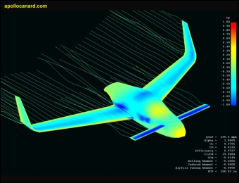
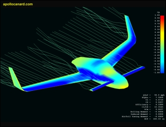
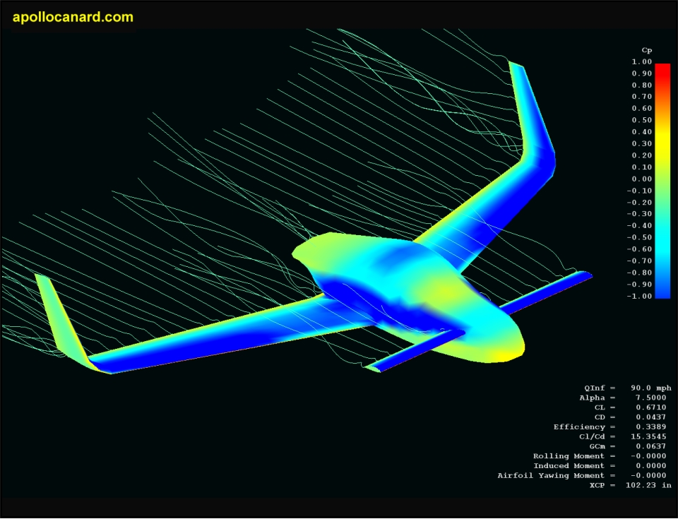
After the aircraft is modeled, the user sets parameters for the desired analysis cases. XFLR5 will display a standard isometric view and
the user selects pressure plots, streamlines, lift distribution, surface velocity, transition lines, etc. to display together or individually.
Some of the entities can also be crudely animated. Here are two screenshots of the Apollo in XFLR5.
For additional screenshots, visit the CFD page in the Photo Gallery section. XFLR5 is also discussed in the Optimizing Blended Winglet
Radii on Homebuilt Canard Aircraft report available on the Download page.
One minor complaint is that recent versions of XFLR5 could not read the polar data that I generated five years ago. If I had not kept
older versions of the program, those files would be useless. We must also point out that XFLR5 analyses can be inaccurate. There
were large (erroneous) spikes in the lift-lines near the Apollo’s fuselage and the blended winglet study uncovered some inconsistent drag
predictions. XFLR5 lacks the rigorous testing and proven analytical capabilities of high-end CFD software. Nobody should rely on it
to determine the neutral point of a real aircraft.
But despite the anomalies, XFLR5 did capture many of the expected characteristics of a canard aircraft. The pressure distribution,
streamlines and other parameters are similar to results from expensive CFD software. I think this program provides valuable insight
during the preliminary design stage and the ease-of-use and low cost cannot be beaten.
Site Map
Email the Designer
Copyright © 2012 Apollo Canard
XFLR5
One of the most valuable tools for designing the wing of my airplane was XFLR5 software. This program provides a graphical user
interface for the text-based XFOIL program, which is fully integrated into XFLR5. The XFOIL kernal provides direct and inverse analysis
capabilities for the design of subsonic airfoils. XFLR5 adds wing design analysis based on Lifting Line Theory and the Vortex Lattice
Method. Recent versions can perform a 3D panel analysis for an entire aircraft. Did I mention the software also makes pretty pictures
and that it’s FREE?
The developer of XFLR5 includes the following disclaimer: “XFLR5 is written exclusively for the design of model sailplanes. The code’s
use for all other purposes, especially for the design of real aircraft, is strongly disapproved. This program is distributed without any
warranty; without even the implied warranty of merchantability or fitness for a particular use”.
Despite the disclaimer, XFLR5 demonstrated impressive results during my usage. Let’s start with airfoil development: The airfoil module
can generate 4 or 5 digit NACA airfoils internally. Over a thousand different airfoils can be loaded from the UIUC airfoil database using
standard .DAT files. The user can change the camber or thickness of airfoils or blend two airfoils into one by interpolation. New airfoils
can be created with splines or by editing the parameters of other airfoils.
Airfoils are analyzed in batch mode to generate their polar data. The data can be displayed in five standard graphs or the user can
specify the variables to be graphed. All the graphs can be formatted with custom colors and lines. If multiple airfoils are opened, XFLR5
displays the analysis results on one graph so the user can make direct comparisons. Polar data for individual airfoils can be exported to
text files for later use in Airplane PDQ, although some editing is required.
There is a learning curve here and XFLR5 will take a couple days or more to master. It helps to have some XFOIL experience or
knowledge of aerodynamics to decide which settings should be used. For example, the Airfoil Optimizer study taught us that default
XFOIL settings will over-predict the maximum lift coefficient, under-predict the minimum drag, and over-predict the nose down pitching
moment. The amount of error can be reduced slightly by entering an appropriate Mach number (don’t leave it at 0.0) and by setting the
Ncrit value to 5 or 7 (don’t use 9).
Once the user has experience with the airfoil commands, the Wing and Plane Design module should be less intimidating. The default
wing-plane settings are sized for an RC model. Designers of real aircraft can enter their aircraft’s data instead. XFLR5 treats the
fuselage as a “body” and it is designed under a different menu command. The default RC sailplane fuselage can be edited or a new
body created. Be patient, it’s going to take some time to learn.
After the aircraft is modeled, the user sets parameters for the desired analysis cases. XFLR5 will display a standard isometric view and
the user selects pressure plots, streamlines, lift distribution, surface velocity, transition lines, etc. to display together or individually.
Some of the entities can also be crudely animated. Here are two screenshots of the Apollo in XFLR5.
For additional screenshots, visit the CFD page in the Photo Gallery section. XFLR5 is also discussed in the Optimizing Blended Winglet
Radii on Homebuilt Canard Aircraft report available on the Download page.
One minor complaint is that recent versions of XFLR5 could not read the polar data that I generated five years ago. If I had not kept
older versions of the program, those files would be useless. We must also point out that XFLR5 analyses can be inaccurate. There
were large (erroneous) spikes in the lift-lines near the Apollo’s fuselage and the blended winglet study uncovered some inconsistent drag
predictions. XFLR5 lacks the rigorous testing and proven analytical capabilities of high-end CFD software. Nobody should rely on it
to determine the neutral point of a real aircraft.
But despite the anomalies, XFLR5 did capture many of the expected characteristics of a canard aircraft. The pressure distribution,
streamlines and other parameters are similar to results from expensive CFD software. I think this program provides valuable insight
during the preliminary design stage and the ease-of-use and low cost cannot be beaten.
Site Map
Email the Designer
Copyright © 2012 Apollo Canard