


 Airfoil Design
“Airfoil optimization requires the application of science, intuition, and perseverance”
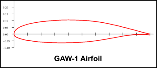
When Burt Rutan designed the Vari-EZ in 1974, he selected NASA’s GA(W)-1 airfoil for the wing. He modified the cusp to reduce its
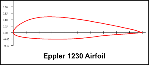
pitching moment, but the section remained a modern (at the time) laminar flow, high-lift airfoil. Burt then designed the Long-EZ in 1978
and selected the Eppler 1230 airfoil, which he also modified to reduce pitching moment. The E1230 is a forward loaded, turbulent flow
airfoil with higher drag than the GAW1. This choice puzzled some observers. Why would Burt specify an older, draggier airfoil for the
Long-EZ?
I learned the answer while investigating the Cozy wing using Airplane PDQ. A pattern developed in the aircraft’s response to different
airfoils. In short, the following airfoil qualities had a major affect on pitch stability and CG range:
•
Lift curve slope. The canard is a flapped airfoil and its lift coefficient (CL) increases at a faster rate than the wing as their angle
of attack increases. This moves the neutral point forward and decreases the stability margin. To combat this, the wing’s airfoil
should have the steepest lift curve possible. For a given set of parameters, the wing’s lift curve determines how far the neutral
point moves forward as alpha increases. The steeper the curve, the farther aft the neutral point will remain.
•
Pitching moment. The wing’s pitching moment determines the aircraft’s forward CG limit. An airfoil with a low moment
coefficient (Cm) will allow the aircraft’s CG to be farther forward. Airfoils with large pitching moments load up the canard and
restrict the forward CG, or they require a larger canard which moves the neutral point forward.
The E1230 airfoil has a steeper lift curve and smaller pitching moment than the GAW1. This maximizes the Long-EZ’s CG envelope and
minimizes the required wing sweep; whereas the Vari-EZ wing needs more sweep to keep the neutral point far enough aft with the GAW1
airfoil. The Long-EZ is also more stable than the Vari-EZ at higher angles of attack.
I didn’t realize how excellent Burt’s choice was until I searched for a replacement. I used Airfoil Optimizer and Airplane PDQ to evaluate
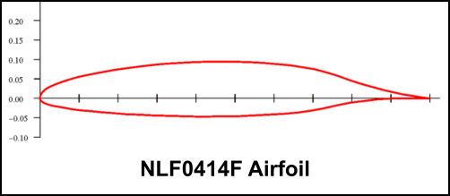
airfoils with low drag and high CL max. Many of the laminar flow airfoils had large moment coefficients (Cm) that resulted in lower cruise
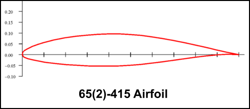
speeds due to high trim drag on the canard. After filtering these out, I found sections like the NLF0414F, GA40A315 and 65(2)-415 that
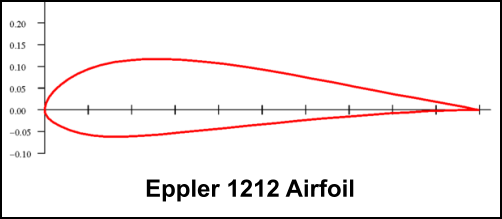
increased cruise speed by 5 to 9 knots along with a small increase in stall speed. I also found the Eppler 1212 airfoil (used on the Q2
and Q200) that lowered stall speed by 2 knots with no impact on cruise speed. No single airfoil increased cruise speed and
lowered stall speed simultaneously.
It was around this time that I decided to abandon the Cozy wing, for reasons described on the Wing Geometry page. Reconfiguring the
wing to eliminate the strake would provide modest efficiency gains all by itself. But the airfoil studies led to an insight that really improved
performance: The wing root should have a laminar flow airfoil optimized for the larger operating RN and the tip airfoil should
be a turbulent flow, high CL max airfoil optimized for the smaller RN!
Using two different airfoils with a smooth transition from root-to-tip would ensure that every section of the wing was optimized for its
respective RN. The inboard span (the larger area) would be dominated by the laminar airfoil and would reduce total wing drag. The
outer span would be dominated by the stall resistant, high CL max, turbulent airfoil. Both airfoils would have a low to moderate moment
coefficient. Later analysis confirmed this configuration was ideal.
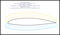
The Apollo’s wing area, taper, sweep and washout are similar to the Cozy, except the Apollo’s mean aerodynamic chord is 33% larger
than the Cozy wing (without the strake). The Apollo’s design lift coefficient at 195 mph is 0.187 after accounting for a 17% loss from wing
sweep. Washout reduces the wingtip CL to zero at cruise speed, so the root airfoil CL must equal 0.37 to approximate 0.187 for the
entire wing. The wing root incidence is tentatively set at +1.0 degree but downwash from the canard reduces this to zero or slightly less.
This means the root airfoil’s design lift coefficient at zero degrees alpha should be 0.37 or higher.
Using Pazmany’s equation for Reynolds Number (RN), the Apollo’s 55” root chord operates at RN of 8.3 million at cruise speed and 3.0
million near stall. Airfoil Optimizer was used to identify airfoils with low drag “buckets” at lift coefficients around 0.4 and with low to
moderate moment coefficients. Candidate airfoils were then analyzed in Airplane PDQ to determine their effect on the aircraft’s total
performance. Dozens of airfoils were evaluated against the Eppler 1230 baseline and each other. The 65(2)-415 came close to being
optimal. For the Apollo application, the cusp was modified to reduce the pitching moment, the camber line was tweaked to increase CL
and to fit the wing spar, and the nose was modified per Riblett’s design method. The new airfoil has a higher L/D ratio at design CL than
the 65(2)-415.
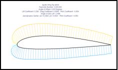
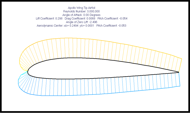
The tip airfoil operates at RN of 4.2M at cruise and 1.5M near stall. To approximate an elliptical lift distribution, the wing tip should
produce zero lift at the design cruise speed. We tentatively set wing twist at 3.2 degrees. The root airfoil has +1.0 deg incidence, so the
tip airfoil must produce zero lift at -2.2 degrees alpha. The tip airfoil should also be stall resistant and achieve high CL max at a relatively
small RN. These requirements favor a forward loaded airfoil with a round nose. Rutan’s modified Eppler 1230 provided a good baseline
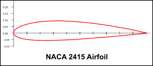
for the tip. After analyzing dozens of alternatives, we found the Eppler 1212 was a strong contender. But the NACA 2415 fit our spar
design better, had less drag at cruise, and had less Cm than the Epplers. After further analysis, the 2415 airfoil thickness was reduced to
14% to lower drag, the nose was updated per Riblett’s method, and the camber line was optimized for high CL max.
All airfoil modifications were performed with XFLR5 software. As a designer (and not an aerodynamicist) I found the following techniques
invaluable:
1.
XFLR5 allows the user to create airfoils by “interpolation”. This function blends two different airfoils into one, with full control over
the mixing percentage. Designers use this method to combine airfoils with different desirable properties into a new airfoil with a
mix of those properties. The result is a compromise, the extent of which is controlled by the user. One airfoil can be influenced by
several others in this way.
2.
The second technique is rather embarrassing. If software did this, it would be called “parametric airfoil optimization using artificial
intelligence”. Since I did it manually, it’s called “the brute force optimization method”. It involves raising or lowering the four airfoil
quadrants (one surface at a time) by a small percentage and then analyzing the effect. “Quadrant” refers to the forward and aft
portion of the upper and lower airfoil surfaces. I promise you will have an intuitive feel for airfoil design trade-offs after using this
method a hundred times or so.
These techniques are less sophisticated than what many aerodynamicists do, but they can still provide excellent results. Airplane PDQ
reports the new airfoils and wing planform increase cruise speed by 8 knots and reduce stall speed by 4 knots compared to the
Cozy wing. And that’s before adding the blended winglets, which PDQ can’t model.
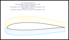
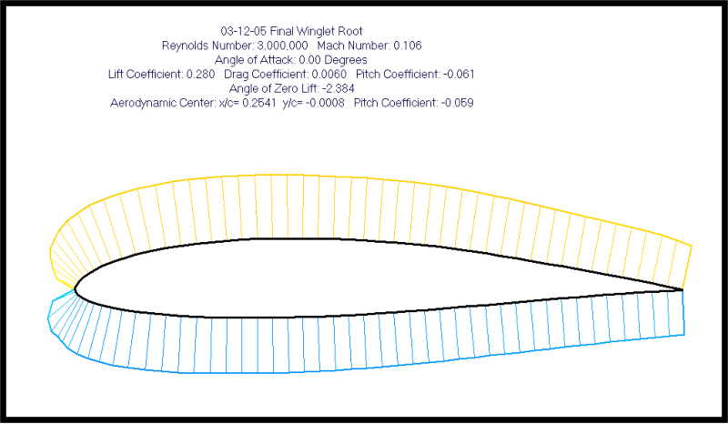
The following pictures (click to enlarge) show the Apollo’s airfoils for the wing root, wing tip and winglet:
Site Map
Email the Designer
Copyright © 2012 Apollo Canard
Airfoil Design
“Airfoil optimization requires the application of science, intuition, and perseverance”
When Burt Rutan designed the Vari-EZ in 1974, he selected NASA’s GA(W)-1 airfoil for the wing. He modified the cusp to reduce its
pitching moment, but the section remained a modern (at the time) laminar flow, high-lift airfoil. Burt then designed the Long-EZ in 1978
and selected the Eppler 1230 airfoil, which he also modified to reduce pitching moment. The E1230 is a forward loaded, turbulent flow
airfoil with higher drag than the GAW1. This choice puzzled some observers. Why would Burt specify an older, draggier airfoil for the
Long-EZ?
I learned the answer while investigating the Cozy wing using Airplane PDQ. A pattern developed in the aircraft’s response to different
airfoils. In short, the following airfoil qualities had a major affect on pitch stability and CG range:
•
Lift curve slope. The canard is a flapped airfoil and its lift coefficient (CL) increases at a faster rate than the wing as their angle
of attack increases. This moves the neutral point forward and decreases the stability margin. To combat this, the wing’s airfoil
should have the steepest lift curve possible. For a given set of parameters, the wing’s lift curve determines how far the neutral
point moves forward as alpha increases. The steeper the curve, the farther aft the neutral point will remain.
•
Pitching moment. The wing’s pitching moment determines the aircraft’s forward CG limit. An airfoil with a low moment
coefficient (Cm) will allow the aircraft’s CG to be farther forward. Airfoils with large pitching moments load up the canard and
restrict the forward CG, or they require a larger canard which moves the neutral point forward.
The E1230 airfoil has a steeper lift curve and smaller pitching moment than the GAW1. This maximizes the Long-EZ’s CG envelope and
minimizes the required wing sweep; whereas the Vari-EZ wing needs more sweep to keep the neutral point far enough aft with the GAW1
airfoil. The Long-EZ is also more stable than the Vari-EZ at higher angles of attack.
I didn’t realize how excellent Burt’s choice was until I searched for a replacement. I used Airfoil Optimizer and Airplane PDQ to evaluate
airfoils with low drag and high CL max. Many of the laminar flow airfoils had large moment coefficients (Cm) that resulted in lower cruise
speeds due to high trim drag on the canard. After filtering these out, I found sections like the NLF0414F, GA40A315 and 65(2)-415 that
increased cruise speed by 5 to 9 knots along with a small increase in stall speed. I also found the Eppler 1212 airfoil (used on the Q2
and Q200) that lowered stall speed by 2 knots with no impact on cruise speed. No single airfoil increased cruise speed and
lowered stall speed simultaneously.
It was around this time that I decided to abandon the Cozy wing, for reasons described on the Wing Geometry page. Reconfiguring the
wing to eliminate the strake would provide modest efficiency gains all by itself. But the airfoil studies led to an insight that really improved
performance: The wing root should have a laminar flow airfoil optimized for the larger operating RN and the tip airfoil should
be a turbulent flow, high CL max airfoil optimized for the smaller RN!
Using two different airfoils with a smooth transition from root-to-tip would ensure that every section of the wing was optimized for its
respective RN. The inboard span (the larger area) would be dominated by the laminar airfoil and would reduce total wing drag. The
outer span would be dominated by the stall resistant, high CL max, turbulent airfoil. Both airfoils would have a low to moderate moment
coefficient. Later analysis confirmed this configuration was ideal.
The Apollo’s wing area, taper, sweep and washout are similar to the Cozy, except the Apollo’s mean aerodynamic chord is 33% larger
than the Cozy wing (without the strake). The Apollo’s design lift coefficient at 195 mph is 0.187 after accounting for a 17% loss from wing
sweep. Washout reduces the wingtip CL to zero at cruise speed, so the root airfoil CL must equal 0.37 to approximate 0.187 for the
entire wing. The wing root incidence is tentatively set at +1.0 degree but downwash from the canard reduces this to zero or slightly less.
This means the root airfoil’s design lift coefficient at zero degrees alpha should be 0.37 or higher.
Using Pazmany’s equation for Reynolds Number (RN), the Apollo’s 55” root chord operates at RN of 8.3 million at cruise speed and 3.0
million near stall. Airfoil Optimizer was used to identify airfoils with low drag “buckets” at lift coefficients around 0.4 and with low to
moderate moment coefficients. Candidate airfoils were then analyzed in Airplane PDQ to determine their effect on the aircraft’s total
performance. Dozens of airfoils were evaluated against the Eppler 1230 baseline and each other. The 65(2)-415 came close to being
optimal. For the Apollo application, the cusp was modified to reduce the pitching moment, the camber line was tweaked to increase CL
and to fit the wing spar, and the nose was modified per Riblett’s design method. The new airfoil has a higher L/D ratio at design CL than
the 65(2)-415.
The tip airfoil operates at RN of 4.2M at cruise and 1.5M near stall. To approximate an elliptical lift distribution, the wing tip should
produce zero lift at the design cruise speed. We tentatively set wing twist at 3.2 degrees. The root airfoil has +1.0 deg incidence, so the
tip airfoil must produce zero lift at -2.2 degrees alpha. The tip airfoil should also be stall resistant and achieve high CL max at a relatively
small RN. These requirements favor a forward loaded airfoil with a round nose. Rutan’s modified Eppler 1230 provided a good baseline
for the tip. After analyzing dozens of alternatives, we found the Eppler 1212 was a strong contender. But the NACA 2415 fit our spar
design better, had less drag at cruise, and had less Cm than the Epplers. After further analysis, the 2415 airfoil thickness was reduced to
14% to lower drag, the nose was updated per Riblett’s method, and the camber line was optimized for high CL max.
All airfoil modifications were performed with XFLR5 software. As a designer (and not an aerodynamicist) I found the following techniques
invaluable:
1.
XFLR5 allows the user to create airfoils by “interpolation”. This function blends two different airfoils into one, with full control over
the mixing percentage. Designers use this method to combine airfoils with different desirable properties into a new airfoil with a
mix of those properties. The result is a compromise, the extent of which is controlled by the user. One airfoil can be influenced by
several others in this way.
2.
The second technique is rather embarrassing. If software did this, it would be called “parametric airfoil optimization using artificial
intelligence”. Since I did it manually, it’s called “the brute force optimization method”. It involves raising or lowering the four airfoil
quadrants (one surface at a time) by a small percentage and then analyzing the effect. “Quadrant” refers to the forward and aft
portion of the upper and lower airfoil surfaces. I promise you will have an intuitive feel for airfoil design trade-offs after using this
method a hundred times or so.
These techniques are less sophisticated than what many aerodynamicists do, but they can still provide excellent results. Airplane PDQ
reports the new airfoils and wing planform increase cruise speed by 8 knots and reduce stall speed by 4 knots compared to the
Cozy wing. And that’s before adding the blended winglets, which PDQ can’t model.
The following pictures (click to enlarge) show the Apollo’s airfoils for the wing root, wing tip and winglet:
Site Map
Email the Designer
Copyright © 2012 Apollo Canard