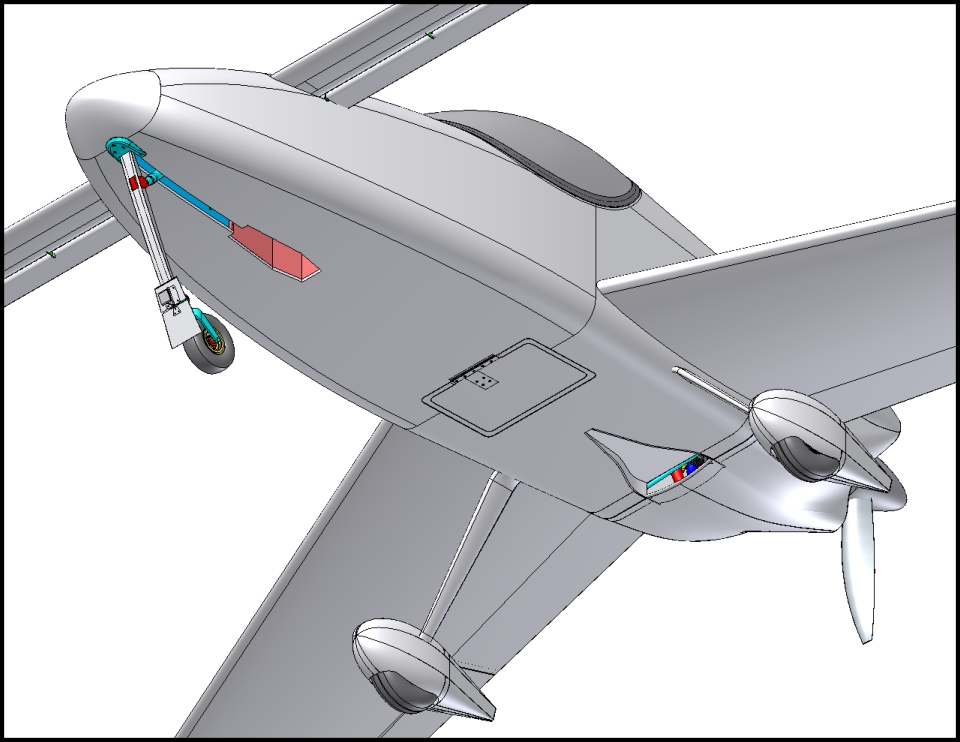
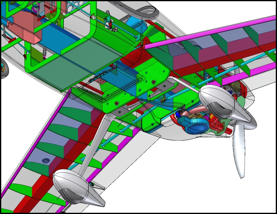
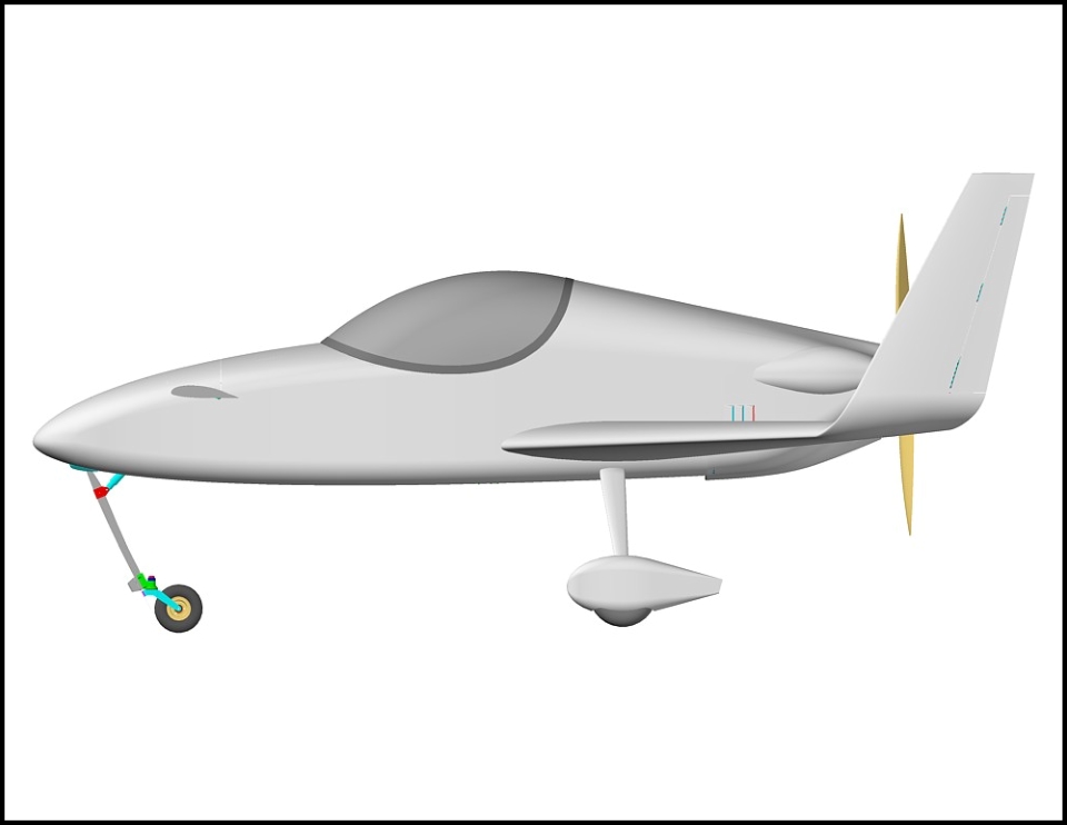
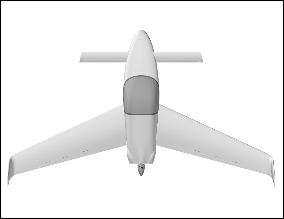
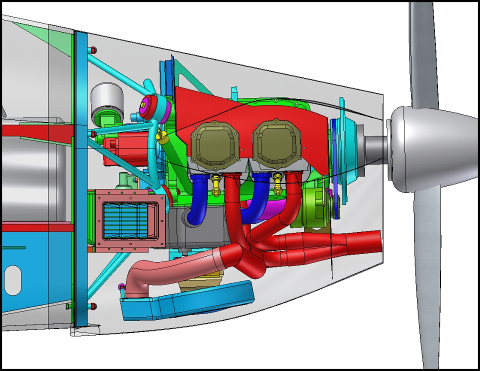
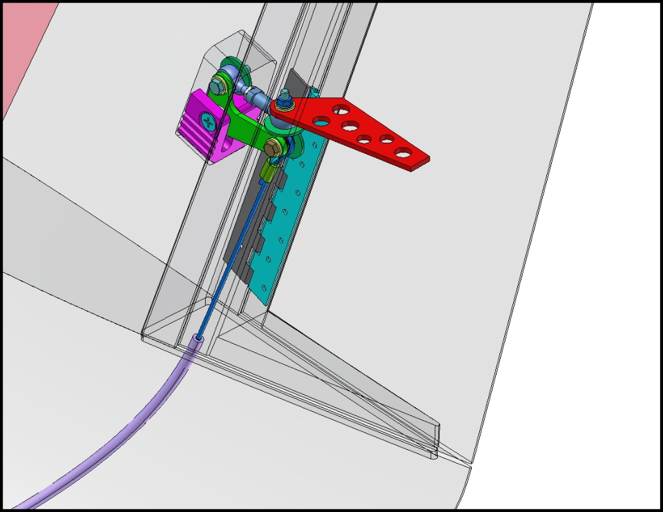
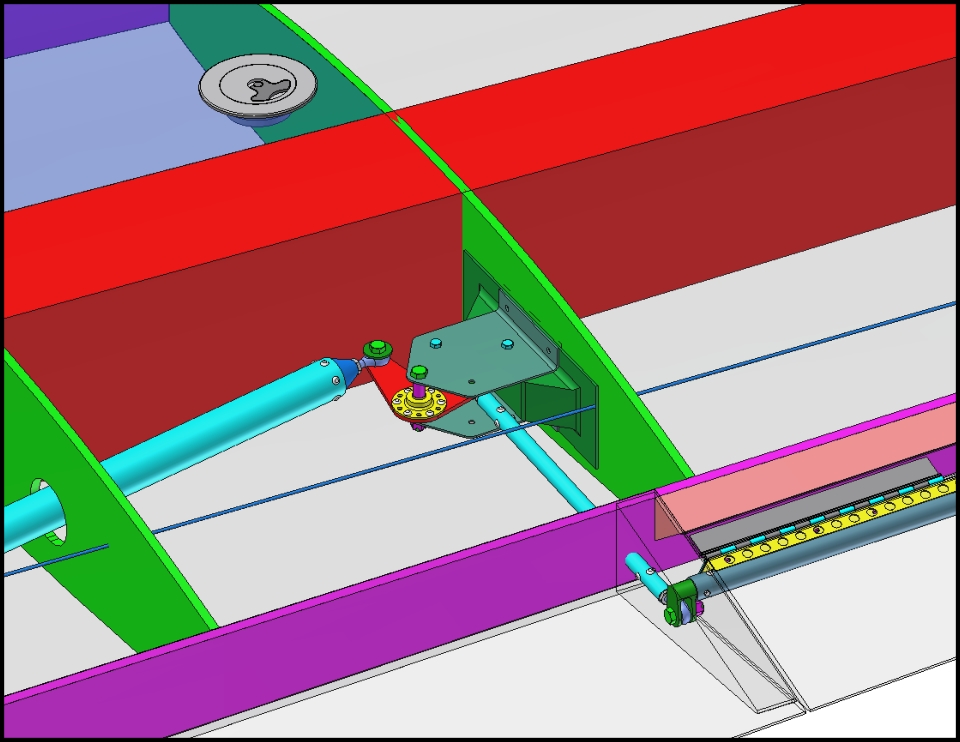
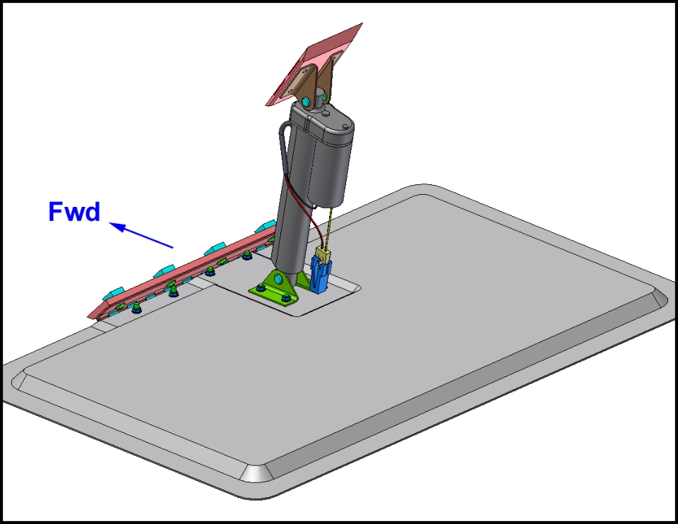
CAD Gallery
Site Map
Email the Designer
Copyright
©
2012 Apollo Canard
Welcome
What's a Canard?
Site Map
Design Goals
Ergonomics
Safety Features
Specifications
Performance
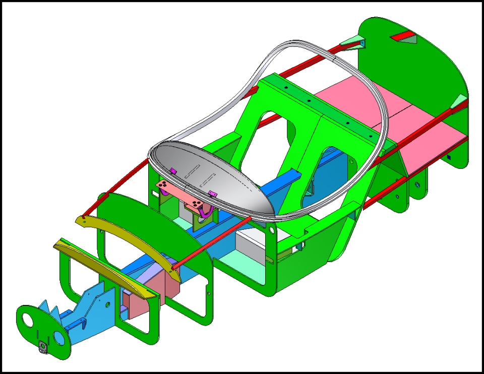
CAD Gallery
CFD Images
FEA Images
Aero Overview
Canard Myths
Wing Geometry
Airfoil Design
Blended Winglets
Deep Stall?
Excel
Airplane PDQ
Airfoil Optimizer
CAD Software
XFLR5
Downloads
Links
FAQs
Meet the Designer
Contact Info